Push-To Telescope System
After spending time with a home-built Dobsonian, I upgraded to an Apertura AD8 — a solid, well-regarded 8-inch Dobsonian that I did not have to design and print myself. It is a great scope, but like any manual Dobsonian, finding objects in the dark still comes down to star hopping and patience.
I wanted a push-to system: a device that tracks where the telescope is pointing and displays live coordinates, so I can look up a target on my phone, push the scope until the numbers match, and be in the neighborhood instead of searching blind. Commercial push-to options exist, but they tend to be expensive, hard to source, and critically several of them require drilling into or otherwise modifying the telescope. I decided building something custom would be easier and probably faster than tracking down a pre-built solution.
The result attaches to the AD8 entirely without permanent modifications. Everything mounts via command strips and snap-in 3D-printed parts. The system is also intentionally simpler than most push-to setups. There is no Stellarium integration, no onboard catalog, no object selection. It is a screen that shows where you are pointing, nothing more.
The Workflow
Observing with the system works like this:
- Power on the device and connect to its Wi-Fi setup server.
- Enter your location, sync the time, and align on one or two known stars.
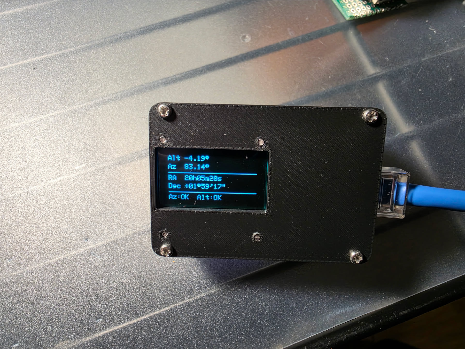
- Setup finishes, Wi-Fi shuts off, and the OLED shows live Alt/Az and RA/Dec.
- Look up your target's coordinates on your phone. (Telescopius, Stellarium, or The Sky Live works well for this)
- Push the telescope until the displayed coordinates match.
- Use the finder or eyepiece to finish centering. You will be close.
The accuracy is good enough that I end up very close to the target most of the time. The last bit of centering takes seconds. Compared to searching an unfamiliar patch of sky from scratch, it is a completely different experience.
Perf Boards
The system started as a breadboard prototype to validate the sensors and coordinate math. Once everything checked out, I soldered each component onto its own perf board. Each board got a small ceramic capacitor (1 nF) and a larger electrolytic capacitor (100 µF) across power and ground to stabilize voltage at each node and keep things clean over the I2C cable runs.
All components communicate over I2C using short CAT5 cable runs. CAT5 was cheap, easy to find, and gave me enough wires to run everything through a single cable. SCL, SDA, and power each run twisted with a ground wire, which helped keep the signals stable enough for this setup while making the telescope wiring more manageable in the field
ESP32-S3 Controller
The brains of the system is a Seeed Studio XIAO ESP32-S3. It runs the Wi-Fi setup server, handles the sensor reads, does the coordinate math, and drives the display. Currently powered by a USB-C phone backup battery; the plan is to eventually integrate a 1100 mAh LiPo with a physical power switch.
Altitude Sensor: MPU-6050
Altitude is measured by an MPU-6050 accelerometer/gyro module mounted on the telescope tube. Only the accelerometer is used (it reads the tilt angle directly). The firmware averages the last ten readings to smooth out jitter and keep the display stable enough to aim by.
Azimuth Encoder: AS5600
Azimuth uses an AS5600 absolute magnetic rotary encoder. A small magnet attaches to azumuth friction adjustment knob; the AS5600 reads its angle directly. Because it is an absolute encoder, it reports the full current position rather than counting incremental movement, so there is no drift to accumulate between power cycles. The firmware calculates an offset during alignment so the reported azimuth is relative to north rather than the magnet's arbitrary starting position.
Display
The display is a 0.96-inch 128x64 OLED running an SSD1306 controller over I2C. Bright enough to read easily, small enough to mount out of the way. I layered green gel filters over the screen to soften the white OLED light. Harsh white at the eyepiece destroys night vision, and the green shift makes glancing at coordinates much more comfortable after dark.
3D-Printed Cases
Every component got its own 3D-printed PLA enclosure. The cases protect the boards, provide clean mounting ' surfaces, and keep the scope looking like a finished tool instead of a science fair victim. Also, the components just look cool as hell in 3D-printed cases.
ESP32 Controller
Altitude Sensor
Display
Azimuth Encoder
The azimuth assembly was the hardest mechanical part of the whole project. The AS5600 needs to sit at a precise distance from the magnet. Too far and readings get unreliable, too close and there is a risk of contact. The mount also needed to be height-adjustable, hold the sensor aligned with the magnet's axis, and attach to the AD8 base without wobbling. It took several design iterations to get all of that right simultaneously.
The magnet itself sits in a knob adapter that fits over the existing azimuth friction knob on the AD8 base, so the magnet rotates with the base while the sensor stays fixed. No drilling, no permanent changes to the scope.
Fully Assembled System
With all four boards soldered and cased, I wired everything together before mounting anything on the telescope. The ESP32 acts as the hub. All three peripheral boards plug into it via CAT5 runs. This was the first time the complete system ran as a unit outside of the breadboard stage.
Installing on the Telescope
Installation on the AD8 required no drilling or permanent modifications. The azimuth knob adapter snaps onto the existing friction knob on the rocker base, and the sensor assembly positions the AS5600 over it. The altitude sensor and display mount on the telescope tube, and the ESP32 controller sits between them with CAT5 runs connecting everything. Command strips and purpose-designed snap-fit prints handle all the attachment points.
Once everything was on the scope and I started testing, I hit the most painful bug of the entire project. The coordinate readouts were wrong, badly wrong, in a way that looked like a serious error in the spherical geometry or the sensor readings. I spent two days going back through the math, the time sync, the alignment code, all of it.
The problem was my longitude. I'm at -103, but I had enetered positive 103 early on in testing. The system had been doing the math correctly the entire time. Rememebr to check all of your inputs before you assume the code is wrong!!
Setup and Calibration
When the device powers on, it hosts a Wi-Fi access point and a small setup server accessible at setup.local. From a phone, you enter your latitude and longitude, sync the current
time, and select alignment stars from a dropdown. The onboard database holds around 450 bright,
fixed stars. Iit exists purely for calibration, not browsing, so planets and deep-sky objects are
intentionally excluded.
There are two alignment modes. One-star alignment does a simple offset and works well when the base is reasonably level. Two-star alignment does a spherical calculation from two reference points, making it much more forgiving when the base is not level. I hate leveling my scope in the field, so I solved that problem in code. Once alignment is saved, the Wi-Fi server shuts off to conserve battery and the OLED takes over.
First Real Use — May 14, 2026
The first real observing session used Pollux as the alignment star. From there I put the system through its paces:
Jupiter: looked up its coordinates on Telescopius and pushed the scope into position. Found it in around 20 seconds. Jupiter was fairly close to Pollux, so it was a good confidence builder but not a brutal test.
Capella: much farther from Pollux. Looked up the coordinates, moved the scope, found it in under a minute. A stronger proof that the system was tracking the sky correctly across a wider range of motion.
M81 and M82: looked up M81's coordinates and moved the scope. Did not see the galaxy immediately; I scanned the area briefly and let my eyes adjust. M81 appeared, and M82 was visible nearby.
The following night I used it to locate M53, a globular cluster in Coma Berenices (the first globular cluster I had ever observed!) The push-to system turned what would have been a difficult star hop into a matter of moving the scope to the right numbers.
What's Next
The system currently runs off a USB-C phone backup battery. The plan is to integrate a 1100 mAh LiPo with a physical power switch for a cleaner, more self-contained setup.